- 您现在的位置:买卖IC网 > Sheet目录868 > LTM4614IV#PBF (Linear Technology)IC UMODULE DC/DC DUAL 4A 144LGA
�� �
�
�LTM4614�
�APPLICATIONS� INFORMATION�
�+� R� FB�
�V� OUT� =� 0.8V� ?�
�ParallelSwitchingRegulatorOperation�
�The� LTM4614� switching� regulators� are� inherently� current�
�mode� control.� Paralleling� will� have� very� good� current� shar-�
�ing.� This� will� balance� the� thermals� on� the� design.� Figure�
�13� shows� a� schematic� of� a� parallel� design.� The� voltage�
�feedback� equation� changes� with� the� variable� N� as� chan-�
�nels� are� paralleled.�
�The� equation:�
�4.99k�
�N�
�R� FB�
�N� is� the� number� of� paralleled� channels.�
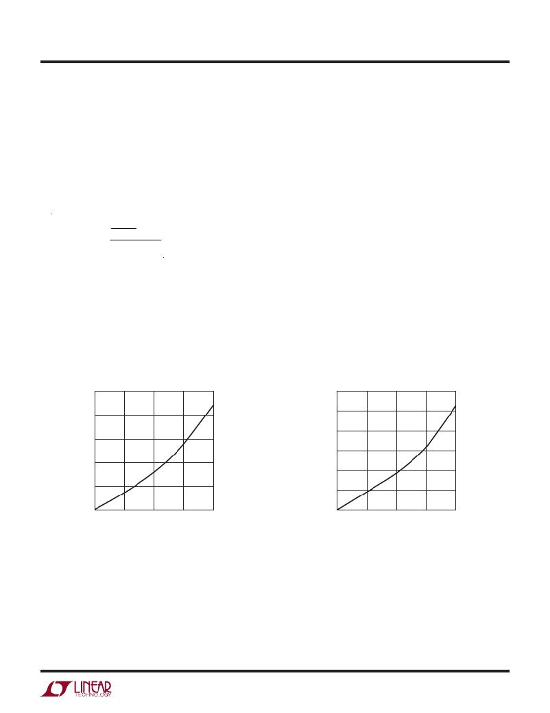
�Thermal� Considerations� and� Output� Current� Derating�
�The� power� loss� curves� in� Figures� 5� and� 6� can� be� used�
�in� coordination� with� the� load� current� derating� curves� in�
�Figures� 7� to� 10� for� calculating� an� approximate� θ� JA� thermal�
�resistance� for� the� LTM4614� with� various� heat� sinking�
�2.5�
�2.0�
�and� airflow� conditions.� Both� of� the� LTM4614� outputs�
�are� at� full� 4A� load� current,� and� the� power� loss� curves� in�
�Figures� 5� and� 6� are� combined� power� losses� plotted� for�
�both� output� voltages� up� to� 4A� each.� The� 4A� output� voltages�
�are� 1.2V� and� 3.3V.� These� voltages� are� chosen� to� include�
�the� lower� and� higher� output� voltage� ranges� for� correlating�
�the� thermal� resistance.� Thermal� models� are� derived� from�
�several� temperature� measurements� in� a� controlled� tem-�
�perature� chamber� along� with� thermal� modeling� analysis.�
�The� junction� temperatures� are� monitored� while� ambient�
�temperature� is� increased� with� and� without� airflow.� The�
�junctions� are� maintained� at� ~120°C� while� lowering� output�
�current� or� power� while� increasing� ambient� temperature.�
�The� 120°C� is� chosen� to� allow� for� a� 5°C� margin� window�
�relative� to� the� maximum� 125°C.� The� decreased� output�
�current� will� decrease� the� internal� module� loss� as� ambi-�
�ent� temperature� is� increased.� The� power� loss� curves� in�
�Figures� 5� and� 6� show� this� amount� of� power� loss� as� a�
�function� of� load� current� that� is� specified� for� both� chan-�
�nels.� The� monitored� junction� temperature� of� 120°C� minus�
�the� ambient� operating� temperature� specifies� how� much�
�3.0�
�2.5�
�2.0�
�1.5�
�1.5�
�1.0�
�1.0�
�0.5�
�0.5�
�0�
�0�
�1�
�2�
�3�
�V� IN� =� 5V�
�4�
�0�
�0�
�1�
�2�
�3�
�V� IN� =� 5V�
�4�
�LOAD� CURRENT� (A)�
�4614� F05�
�LOAD� CURRENT� (A)�
�4614� F06�
�Figure� 5.� 1.2V� Power� Loss�
�Figure� 6.� 3.3V� Power� Loss�
�4614fb�
�11�
�发布紧急采购,3分钟左右您将得到回复。
相关PDF资料
LTM4615IV#PBF
IC SWIT REG BUCK 4A ADJ 144LGA
LTM4618IV#PBF
IC DC-DC UMODULE BUCK 6A 84-LGA
LTM4619IV#PBF
IC SWIT REG BUCK 4A ADJ 144LGA
LTM4627MPY#PBF
IC DC/DC UMODULE 15A 133-BGA
LTM4628EV#PBF
IC DC/DC UMODULE 16A 144-LGA
LTM8008HV#PBF
IC DC/DC UMODULE 16-LGA
LTM8020IV#PBF
IC DC/DC UMODULE 200MA 21-LGA
LTM8023MPV#PBF
IC BUCK SYNC ADJ 2A 50LGA
相关代理商/技术参数
LTM4614IVPBF
制造商:Linear Technology 功能描述:Conv DC-DC Dual Step-Down 5.5V LGA144
LTM4615
制造商:LINER 制造商全称:Linear Technology 功能描述:三路輸出、低電壓DC/DC μModule 穩壓器,LTM®4615 是一款具有一個額外 1.5A VLDO (非常低壓差)線性穩壓器的完整 4A 雙路輸出開關模式 DC/DC 電源
LTM4615EV
制造商:LINER 制造商全称:Linear Technology 功能描述:Triple Output, Low Voltage DC/DC μModule Regulator
LTM4615EV#PBF
功能描述:IC SWIT REG BUCK 4A ADJ 144LGA RoHS:是 类别:电源 - 板载 >> DC DC Converters 系列:µModule® 设计资源:VI-200, VI-J00 Design Guide, Appl Manual 标准包装:1 系列:* 类型:隔离 输出数:1 电压 - 输入(最小):66V 电压 - 输入(最大):160V Voltage - Output 1:12V Voltage - Output 2:- Voltage - Output 3:- 电流 - 输出(最大):* 电源(瓦) - 制造商系列:50W 电压 - 隔离:* 特点:* 安装类型:通孔 封装/外壳:9-FinMod 尺寸/尺寸:4.60" L x 1.86" W x 0.79" H(116.8mm x 47.2mm x 20.1mm) 包装:散装 工作温度:-25°C ~ 85°C 效率:* 电源(瓦特)- 最大:*
LTM4615EVPBF
制造商:Linear Technology 功能描述:Conv DC-DC Triple-Out Step Down
LTM4615IV
制造商:LINER 制造商全称:Linear Technology 功能描述:Triple Output, Low Voltage DC/DC μModule Regulator
LTM4615IV#PBF
功能描述:IC SWIT REG BUCK 4A ADJ 144LGA RoHS:是 类别:电源 - 板载 >> DC DC Converters 系列:µModule® 设计资源:VI-200, VI-J00 Design Guide, Appl Manual 标准包装:1 系列:* 类型:隔离 输出数:1 电压 - 输入(最小):66V 电压 - 输入(最大):160V Voltage - Output 1:12V Voltage - Output 2:- Voltage - Output 3:- 电流 - 输出(最大):* 电源(瓦) - 制造商系列:50W 电压 - 隔离:* 特点:* 安装类型:通孔 封装/外壳:9-FinMod 尺寸/尺寸:4.60" L x 1.86" W x 0.79" H(116.8mm x 47.2mm x 20.1mm) 包装:散装 工作温度:-25°C ~ 85°C 效率:* 电源(瓦特)- 最大:*
LTM4615IVPBF
制造商:Linear Technology 功能描述:Conv DC-DC Triple Step-Down 5.5V LGA144